Hydraulic machinery turns pressurized fluid into controlled movement, from a loader’s lifting arm to a factory press. The hydraulic flow control valve regulates how quickly fluid moves through a circuit, shaping actuator speed and response. Small component. Big effect. A slight adjustment can change how smoothly a cylinder extends, while a blocked passage can create unwanted heat and pressure.
The scale of the sector helps explain why these components matter. Grand View Research’s Hydraulic Equipment Market report estimated the global market at USD 43.6 billion in 2022 and projected growth through 2030. That figure covers hydraulic equipment broadly; it is not a valve-only estimate. Still, it reflects the wide use of fluid power in mobile machinery and industrial systems. ISO 4413:2010 also sets general rules and safety requirements for hydraulic fluid-power systems, underscoring that flow adjustment must fit the complete circuit.
In practice, a valve’s behavior depends on more than its dial or orifice. Pressure, fluid viscosity, contamination, and load all influence actual flow. A setting that works on a cool test bench may behave differently after hours of operation. That detail is easy to overlook. This guide explains what a hydraulic flow control valve does, how common designs meter flow, and what engineers should check when selecting or adjusting one. The aim is practical understanding, not a promise that one valve suits every circuit.
A hydraulic flow control valve regulates how quickly oil moves through a hydraulic circuit. By adjusting the opening available to the fluid, it helps set the speed of an actuator, such as a cylinder extending under load. It does not simply “set pressure”: pressure develops in response to resistance in the circuit. Small distinction. A technician might turn an adjustment screw, then watch a cylinder move more slowly while checking for leaks and excess heat.
Inside a basic valve, a narrowed passage restricts flow; a pressure-compensated design also adjusts that passage as pressure changes, helping maintain a steadier flow rate. The exact behavior depends on valve type, oil viscosity, load, and circuit layout. In practice, a clean schematic rarely captures every variable. Throttling can also turn useful hydraulic power into heat, so flow control is not automatically energy efficient. The U.S. Department of Energy’s 2006 report, Improving Pumping System Performance: A Sourcebook for Industry, states that pumping systems account for nearly 20% of global electricity demand and 25–50% of energy use in some industrial plants. Those figures describe pumping systems broadly, not flow control valves specifically, but they underline why fluid movement and energy losses deserve careful attention.
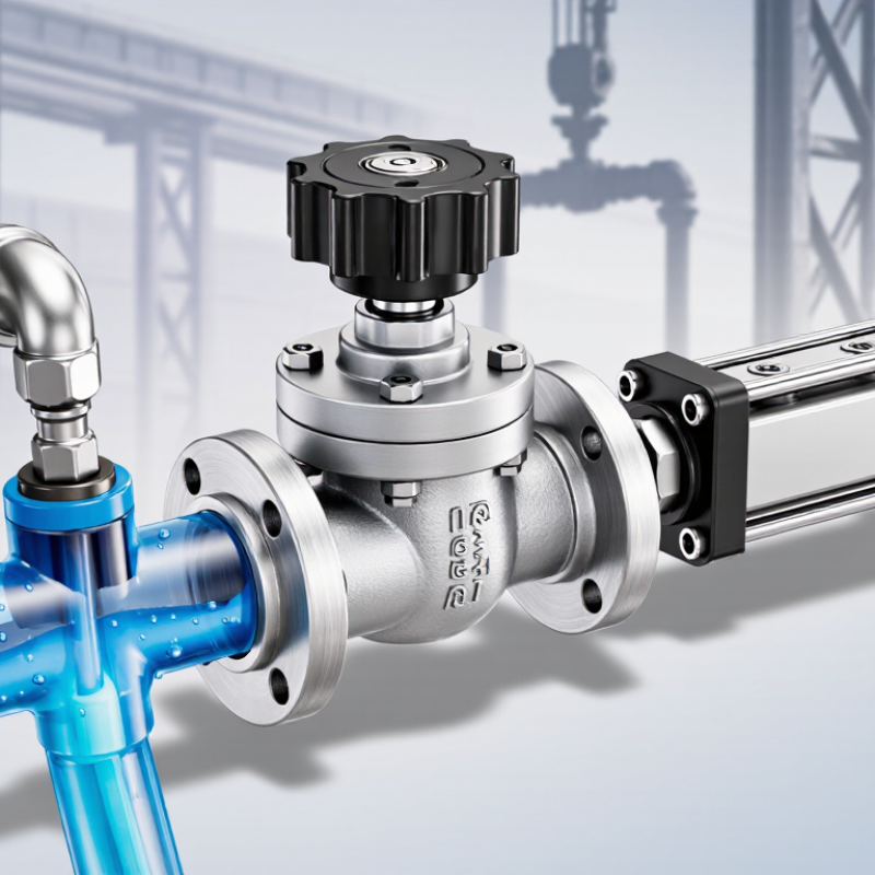
A hydraulic flow control valve regulates how much oil passes through a circuit, helping set an actuator’s speed. Its valve body contains inlet and outlet ports, plus a narrow internal passage. A metering element, such as a needle or spool, changes the passage opening. A small adjustment can noticeably change cylinder movement. That sensitivity is easy to underestimate.
Some valves include a pressure compensator, usually a spring-loaded spool. It adjusts the opening as pressure changes, helping maintain steadier flow under varying loads. A basic, non-compensated valve does not do this, so actuator speed may shift when the load changes. Seals help prevent internal and external leakage. Designs vary, so check the valve’s specifications before matching it to a circuit.
Tips: Adjust flow gradually, then observe the actuator under its real working load. Keep oil clean; contamination can affect small metering clearances. Don’t assume a speed change always means the valve is faulty. I’d check pressure, load, and filter condition too.
A hydraulic flow control valve regulates how much oil passes through a circuit over time. In many designs, a movable spool or adjustable needle changes the opening through which oil flows. A smaller opening usually means less flow and slower actuator movement. A larger opening allows more oil through. Small changes matter.
The valve controls flow by creating a pressure drop across its opening. With a simple throttle valve, changes in load or pressure can also change the flow rate. Pressure-compensated designs use an internal mechanism to help maintain a steadier flow despite pressure changes. They are not perfectly constant under every condition. Oil temperature, contamination, and wear can affect performance.
In a machine, the valve may set how quickly a cylinder extends or a motor turns. For example, reducing flow can make a lifting cylinder rise more slowly, but it does not directly set the force available; system pressure and load matter too. The valve’s location also matters. Meter-in control restricts oil entering an actuator, while meter-out control restricts returning oil and can improve control with some loads. Throttling converts some hydraulic energy into heat, so prolonged restriction may warm the oil. Real circuits can behave less neatly than diagrams suggest. Checking flow, pressure, and temperature during operation helps confirm that the selected setting suits the actual load.
| Valve or Feature | How It Regulates Flow | Pressure Compensation | Typical Use | Key Operating Consideration |
|---|---|---|---|---|
| Fixed-orifice flow control valve | A fixed opening restricts oil flow. Flow depends mainly on the opening size and the pressure difference across it. | No | Simple circuits where load and pressure conditions do not vary greatly. | Flow can change when load pressure or oil viscosity changes. |
| Adjustable, non-compensated flow control valve | A hand-adjusted needle or spool changes the metering opening to set the flow rate. | No | Adjusting actuator speed in basic hydraulic systems. | The setting controls the restriction, but does not guarantee constant flow as pressure changes. |
| Pressure-compensated flow control valve | A compensator varies the metering opening to maintain a nearly constant pressure drop across the metering element. | Yes, within the valve’s operating range | Maintaining a more consistent actuator speed when load pressure varies. | Compensation requires sufficient inlet pressure; flow may fall if available pressure is inadequate. |
| One-way flow control valve with check valve | A metering element restricts flow in one direction, while an integral check valve provides a freer path in the opposite direction. | Depends on the metering design | Controlling speed in one direction while allowing faster return movement. | Confirm the valve’s marked flow direction and check-valve cracking pressure. |
| Meter-in arrangement | A flow control valve meters oil entering an actuator, limiting the rate at which it extends or rotates. | Depends on the selected valve | Loads that resist movement and do not tend to overrun the actuator. | Overrunning loads can cause loss of control; another circuit arrangement may be needed. |
| Meter-out arrangement | A flow control valve meters oil leaving an actuator, controlling its movement by restricting exhaust flow. | Depends on the selected valve | Controlling overrunning or assisting loads in many actuator circuits. | Restricting return flow can raise actuator-side pressure; components must be rated accordingly. |
| Bleed-off arrangement | A flow control valve diverts part of pump flow back to the tank; the remaining flow is available to the actuator. | Depends on circuit design | Speed control in circuits where diverted flow can return to tank efficiently. | Actuator flow depends on pump output and the amount diverted; account for heat and energy losses. |
| Basic flow relationship | For a metering orifice, flow is broadly related to opening area and the square root of the pressure difference across the opening. | A compensator helps stabilize the pressure difference | Explaining why valve opening, pressure, and fluid properties affect flow. | Actual flow also depends on valve geometry, fluid density, viscosity, and operating conditions. |
Hydraulic flow control valves regulate actuator speed by restricting or directing oil flow. A simple throttle valve uses an adjustable needle to narrow an orifice. Turn the needle, and less oil passes each second. In a meter-in arrangement, the valve controls oil entering a cylinder or motor. Meter-out control restricts returning oil, helping manage overrunning loads. Small changes matter. A cylinder may move unevenly if its load shifts or oil temperature changes.
Bleed-off circuits divert part of the pump flow back to the reservoir, leaving the remainder for the actuator. Pressure-compensated flow controls maintain a steadier flow when pressure varies, which can improve speed consistency.
A check valve is often built into the assembly to allow free flow in the opposite direction. That detail can make a machine retract faster. Valves may sit in series with an actuator or in parallel branches serving separate functions. Series arrangements can affect downstream flow; parallel circuits need careful balancing.
In practice, the chosen method depends on load behavior, heat, and required precision. A setting that works on a cool test bench may drift after hours of operation.
In mobile equipment, a hydraulic flow control valve sets how quickly oil reaches an actuator. On an excavator, metered flow can help a boom rise smoothly instead of jerking under load. In a forklift, it can regulate mast speed; in a farm machine, it can control a cylinder moving an implement. Small adjustments matter. Operators feel them at the lever.
Factory systems use these valves in presses, injection-molding machines, and material-handling equipment, where controlled actuator speed supports repeatable motion. A pressure-compensated valve can help maintain a set flow as system pressure changes; a one-way flow control can restrict movement in one direction while allowing freer return flow. The U.S. Department of Energy’s 2022 Industrial Decarbonization Roadmap identifies industry as responsible for roughly 30% of U.S. greenhouse-gas emissions. That figure is not specific to hydraulics, but it gives energy losses in industrial equipment useful context. Throttling flow can waste energy as heat. That trade-off deserves attention. In real systems, sizing, oil temperature, contamination, and load changes all affect performance; a valve setting that works on a test bench may need adjustment on the machine.
Illustrative flow response as a pressure-compensated valve setting changes
A flow control valve meters hydraulic fluid to regulate actuator speed. In this illustrative example, flow rises with the valve setting at a stable pressure differential, reaching 30 L/min at full setting; actual flow depends on valve design and system conditions. These valves are used to control cylinder or motor speed in mobile equipment, machine tools, industrial presses, and material-handling systems.
Accreditations
ISO 9001 Quality Management
HSE Management Compliant
Products and services comply with relevant Australian (AS) and international (ISO, etc.) Standards.
"*" indicates required fields