
7 Tips for Choosing Cemented Carbide Inserts?

Choosing Cemented Carbide Inserts is not just a matter of picking the hardest grade. The right choice depends on the workpiece, cutting conditions, machine rigidity, and the finish you need. A stainless-steel part, for example, may demand a different grade and geometry than a cast-iron component. Even a small change in coolant flow or tool overhang can affect insert life.

Manufacturing technology researcher Professor H. K. Tönshoff has written extensively about machining. I cannot verify a direct quotation from him on insert selection, so the following is an editorial takeaway, not his verbatim words: “A cutting tool performs well only when its material, geometry, and operating conditions work together.” That principle frames these seven tips. They examine how to match insert grade and shape to your material, choose a suitable chipbreaker, and assess coating, cutting speed, and feed. They also consider stability and cost per part, not just the insert’s purchase price. Small details matter. A shiny coating cannot compensate for a setup that chatters, and a durable grade may still produce poor results when its geometry is unsuitable. Use the recommendations as a starting point, then check them against your machine, manufacturer data, and actual cutting results. One test may not settle the question. Careful observation helps.
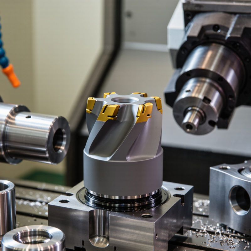
7 Tips for Choosing Cemented Carbide Inserts?

Identify the Workpiece Material and Its Machinability

Identify the workpiece before selecting an insert. ISO 513:2015 classifies common machining materials into groups such as steel, stainless steel, cast iron, non-ferrous alloys, and hardened materials. That label is only a starting point. Check hardness, heat treatment, inclusions, and whether the material work-hardens during cutting. A soft-looking alloy can still be abrasive.

Thermal behavior matters, too. ASM Handbook property tables place pure aluminum near 237 W/m·K, while many austenitic stainless steels are around 15 W/m·K at room temperature; alloy values vary. In practice, aluminum often carries heat away with the chip, while stainless steel can leave more heat near the cutting edge.

Small detail. Big difference.

For a silicon-rich aluminum casting, abrasion may drive edge wear; for gummy stainless, built-up edge and work-hardening deserve attention. Match carbide grade, edge preparation, and chip-breaker geometry to those risks, then verify with a controlled test cut.

One imperfect habit is choosing by material name alone. Two alloys in the same family can behave very differently. Record the actual grade, hardness, and cutting conditions before comparing insert life.

Match Insert Shape and Geometry to the Cutting Operation

Match the insert shape to the cut, not just the material. A square insert offers strong corners for straight turning and facing, where the tool has enough clearance. An 80-degree diamond shape can handle general turning and leave useful access near shoulders. For tighter profiles, a 55-degree diamond reaches into corners more easily, but its sharper point is less robust under heavy loads. Fit matters.

Geometry matters too. A positive rake can reduce cutting pressure on a less rigid machine, while a negative rake often provides a stronger cutting edge when the setup is stable. Choose the nose radius with the finish and rigidity in mind: a larger radius can improve surface finish, but may cause chatter on a slender workpiece. Chipbreakers should suit the feed and depth of cut; a chipbreaker made for light finishing may clog or wear quickly during roughing. Not always obvious.

Before ordering, check the insert’s shape, clearance angle, and chipbreaker against the toolholder and operation. A quick test cut can reveal problems that a catalog chart cannot, such as a shoulder rubbing or chips wrapping around the part. Record the feed, depth, and finish. Then adjust one variable at a time.

7 Tips for Choosing Cemented Carbide Inserts? - Match Insert Shape and Geometry to the Cutting Operation

Tip Cutting operation Suitable insert shape Geometry to consider Selection guidance
1. Start with the operation General external turning 80° diamond (C-style) A general-purpose chipbreaker; choose a positive rake for lower cutting forces or a stronger, more negative geometry for heavier cuts. The robust included angle suits a broad range of turning tasks. Check that the holder and workpiece clearance accommodate the insert.
2. Prioritize access for profiling Contour turning and profiling 55° diamond (D-style) or 35° diamond (V-style) A sharper included angle and suitable clearance can improve access to contours; use a positive-rake geometry when lower cutting forces are important. Narrower-angle inserts reach tighter profiles, but have less edge support. Confirm clearance and avoid excessive depth or impact for the chosen edge strength.
3. Match the edge to shoulders Facing and turning square shoulders 90° square (S-style) or 80° diamond (C-style), depending on access Select a tool approach angle and insert clearance that allow the tool to reach the shoulder without rubbing. A stable edge is useful for interrupted cuts. Check the holder orientation and machine clearance. The insert shape alone does not guarantee a true square shoulder.
4. Choose a corner radius for the finish and load Finishing or rough turning Shape suited to the profile, with an appropriate nose radius A smaller nose radius can reduce cutting forces and help with fine details; a larger radius generally strengthens the corner and can support a higher feed when the setup is rigid. Balance finish requirements against chatter risk, feed rate, workpiece rigidity, and corner strength. Follow the insert maker’s recommended cutting data for the specific grade and geometry.
5. Consider a round edge for milling Face milling and other milling cuts with changing engagement Round (R-style) insert A circular cutting edge distributes load over a changing contact area; select a suitable rake and edge preparation for the material and cut. Round inserts can be effective in milling, but cutting forces can be substantial. Check power, rigidity, engagement, and the recommended depth of cut.
6. Match chip control to the cut Finishing, medium turning, or roughing Any compatible shape with an operation-specific chipbreaker Chipbreaker grooves are designed for particular ranges of feed and depth of cut. Finishing geometries often suit lighter cuts; roughing geometries are typically more robust. Choose a chipbreaker for the actual feed, depth, material, and cutting direction. If chips are long or the edge wears unusually, review the geometry and cutting conditions.
7. Verify the full setup Any turning or milling operation Shape that fits the holder, tool path, and workpiece access Check insert clearance, edge preparation, rake, corner radius, clamping, and whether the cut is continuous or interrupted. Treat shape and geometry as part of a complete tool system. Confirm compatibility with the holder and use cutting data appropriate to the workpiece material and machine setup.

Note: Insert performance depends on the carbide grade, coating, workpiece material, machine rigidity, and cutting conditions as well as shape and geometry.

Select a Carbide Grade for the Cutting Conditions

A carbide grade should match the way the tool meets the workpiece, not just the material name on a job sheet. For a continuous cut in hardened steel, a wear-resistant grade can help maintain the edge at higher cutting speeds. If the cut includes scale, keyways, or interrupted contact, a tougher grade may better resist chipping. These conditions are different. A grade that performs well on a steady pass may fail quickly when it strikes a hard interruption.

Check the workpiece hardness, cutting speed, feed, depth of cut, and coolant use together. For example, a small insert cutting a scaled steel bar may need more toughness than a larger insert making a clean finishing pass. Coating can also affect heat and wear, but it cannot compensate for a poor grade match. Watch the chips and inspect the cutting edge after a short trial. Flank wear suggests a different issue than a chipped corner. Not always obvious. I would change one setting at a time and record the result; real shop conditions can make a recommendation look better on paper than it performs in the cut.

Choose a Coating to Balance Wear and Heat Resistance

A coating should match the heat pattern of the cut, not just the workpiece hardness. TiN suits moderate temperatures, while TiAlN is often chosen for dry or high-speed cutting because aluminum-rich coatings form an oxide barrier as they heat. A review by Mayrhofer and colleagues in Progress in Materials Science (2006) discusses this protective oxidation behavior; reported oxidation limits for TiAlN are often around 800°C, but vary with coating composition and test conditions. That is not a safe operating temperature for every insert.

Watch the chip and cutting edge. A stable, blue chip can indicate substantial heat, while a polished flank or growing notch may point to abrasion or localized wear. For interrupted cuts, a tough PVD coating may tolerate edge impacts better than a thicker, brittle layer. In steady turning, a CVD coating can provide stronger wear protection. Small details matter. Coolant, feed, and chip thickness can shift the balance, so a coating that works in one setup may fail in another.

ISO 513:2012 classifies hard cutting materials by application, including grades for different cutting conditions; it supports selecting by operation rather than by coating label alone. Start with the supplier’s recommended speed range, then test one variable at a time. Record edge wear after a fixed cutting interval. I would not treat color as proof of coating failure; inspect the edge under magnification. The awkward part is that shop tests rarely control every variable perfectly. Keep that limitation in the log.

Choosing a Cemented Carbide Insert Coating: Balance Wear and Heat Resistance

Relative selection guide on a 1–5 scale, not standardized test data. TiCN is commonly selected for wear resistance, while Al₂O₃ and TiAlN/AlTiN coatings are suited to higher-heat cutting conditions. Actual performance depends on coating formulation, insert grade, workpiece material, and cutting conditions.

Check Insert Size, Compatibility, and Cutting Parameters

7 Tips for Choosing Cemented Carbide Inserts?

Tip 1: Check the insert size against the holder’s specifications. Confirm its shape, inscribed circle, thickness, and nose radius. A close match is not enough; the insert must seat flat and clamp securely. Fit matters.

Tip 2: Verify compatibility with the workpiece material and cutting operation. A chipbreaker suited to continuous turning may perform poorly in interrupted cuts. Check clearance and holder geometry, too. An insert that fits physically can still cut badly.

Tip 3: Set cutting parameters for the material, machine, and setup. Use the insert maker’s data as a starting point, not a guarantee. Begin conservatively, then watch chip shape, surface finish, and edge wear. Change one variable at a time. Keep notes. A stable setup may tolerate higher feed, while a slender workpiece may chatter even at modest speeds. There is no universal setting, and charts can feel overly neat compared with a real, vibrating machine. Recheck the edge after the first few passes. Stop and reassess if chips become tangled or the cut grows noisy.

Enquire Today

"*" indicates required fields