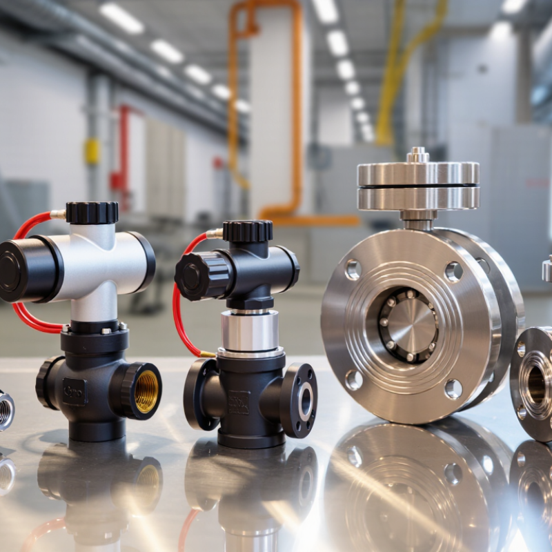
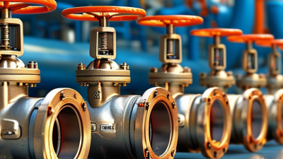
Choosing the right pneumatic valve in 2026 requires more than comparing prices or catalog photographs. Global buyers must consider pressure range, media compatibility, response speed, installation space, and maintenance access. A valve that performs well on a clean factory line may fail early in a dusty packaging plant. Small details matter.
This guide examines the leading pneumatic valve types used across manufacturing, process control, automation, and fluid handling. It explains how directional control valves, solenoid valves, proportional valves, butterfly valves, ball valves, and diaphragm valves differ in practical service. Each section connects valve design with real operating conditions, including cycling frequency, temperature changes, compressed-air quality, and actuator load. Clear selection criteria can reduce downtime and avoid costly replacements.
Still, no universal choice exists. That is the difficult part. Even experienced procurement teams can overlook seal material, port size, or regional documentation requirements. A lower purchase price may create higher energy and service costs later. This overview therefore combines engineering principles with buyer-focused experience, including supplier evaluation, testing records, material certificates, warranty terms, and spare-parts availability. Readers should verify technical data against the actual system and applicable regional standards. Specifications can change, and product pages are not always complete. Careful questions remain essential. The goal is not to promote one design, but to help global buyers make safer, more reliable, and better-informed pneumatic valve decisions in 2026.
What Are Pneumatic Valves and How Do They Work?
Pneumatic valves control compressed air inside automation systems. They direct, start, stop, or exhaust airflow. A valve receives a control signal, then moves an internal spool, poppet, or diaphragm. That movement changes the air path. The air then drives a cylinder, gripper, or rotary actuator.
Common designs include two-way, three-way, and five-way valves. A two-way valve switches airflow on or off. A three-way valve controls single-acting cylinders. A five-way valve usually operates double-acting cylinders, moving them forward or backward. Solenoid, manual, mechanical, and pilot-operated versions suit different control conditions. In practice, port labels matter more than appearance. One wrong connection can reverse motion or create a dead cylinder.
The U.S. Department of Energy reports that compressed air may represent 10% to 15% of industrial electricity use. It also notes that leaks can waste 20% to 30% of compressor output. This makes valve selection an energy decision, not only a controls decision. MarketsandMarkets estimates the pneumatic valves market will grow from about USD 10.3 billion in 2023 to USD 13.6 billion by 2028. Buyers should check flow rate, pressure range, response time, sealing material, and air cleanliness. ISO 8573-1 classifications help define compressed-air quality. Yet real installations are rarely perfect. Undersized tubing, moisture, and poor exhaust routing still cause avoidable failures.
2026 Top Pneumatic Valve Types for Global Buyers
How to Classify the Main Pneumatic Valve Types
Classifying pneumatic valves starts with their control function, not their catalog name. Directional control valves manage airflow between ports and actuators. Common configurations include 2/2, 3/2, 5/2, and 5/3 valves. The first number shows ports, while the second shows switching positions. A 3/2 valve often operates a single-acting cylinder. A 5/2 valve usually controls a double-acting cylinder.
Valve construction creates another useful classification. Spool valves provide flexible switching and many port arrangements. Poppet valves can offer strong sealing and quick response. Flow control valves regulate actuator speed through adjustable air restriction. Pressure control valves protect circuits, reduce supply pressure, or maintain stable operation. Process valves, including ball, butterfly, and diaphragm designs, use pneumatic actuators to control liquids, gases, or powders.
Selection requires more than matching thread size. Check working pressure, temperature, air quality, response time, seal material, and connection standards. The required fail position also matters during air loss. In field installations, I have seen incorrect port labeling cause slow cylinders and unexpected movement. That mistake is easy to miss. Classification is not always clean, either. A valve may belong to a process category mechanically, but its actuator and control circuit need separate evaluation. Buyers should verify drawings, testing records, and operating conditions before approval. A short bench test can reveal leakage, delay, or unsuitable spring behavior.
| Valve Type | Primary Function | Typical Port / Position Classification | Common Actuation | Typical Pneumatic Application | Main Selection Criteria | Key Advantages | Important Limitations |
|---|---|---|---|---|---|---|---|
| 2/2-Way Directional Valve | Starts or stops compressed-air flow between two ports. |
2 ports
2 positions Normally closed or normally open; on/off service. |
Solenoid, pneumatic pilot, manual, mechanical, or spring return. | Air isolation, blow-off control, simple actuator supply, and vacuum-generator control. | Port size, flow coefficient, pressure range, response time, seal material, and electrical voltage where applicable. | Simple construction, easy control logic, and broad availability in compact sizes. | Cannot independently control two actuator directions; throttling is generally not its intended function. |
| 3/2-Way Directional Valve | Controls a single-acting cylinder or switches one signal between supply, exhaust, and an actuator port. |
3 ports
2 positions Normally closed, normally open, or selector configurations. |
Solenoid, pneumatic pilot, pushbutton, roller lever, foot pedal, or spring return. | Single-acting cylinders, pneumatic signals, air pilot circuits, and small clamps. | Normal position, exhaust arrangement, flow rate, mounting method, and required actuation force. | Efficient control of single-acting actuators and control signals with automatic spring return. | Normally unsuitable for independently driving both sides of a double-acting cylinder. |
| 4/2-Way Directional Valve | Reverses airflow to operate a double-acting actuator. |
4 ports
2 positions Supply, exhaust, and two actuator connections. |
Pneumatic pilot, manual, mechanical, or solenoid-assisted actuation. | Double-acting cylinders, rotary actuators, and applications requiring two fixed motion directions. | Actuator volume, cycle speed, port arrangement, pressure drop, and control method. | Provides straightforward forward-and-reverse actuator control with relatively simple circuitry. | Offers fewer center-positioning options than a 5/3 valve and may require separate exhaust management. |
| 5/2-Way Directional Valve | Directs supply and exhaust air to opposite sides of a double-acting actuator. |
5 ports
2 positions One supply port, two actuator ports, and two exhaust ports. |
Single-solenoid spring return, double-solenoid, pneumatic pilot, or manual actuation. | Industrial automation, pick-and-place equipment, packaging machines, and pneumatic grippers. | Flow capacity, switching frequency, coil voltage, manual override, mounting style, and exhaust configuration. | Separate exhaust ports allow better speed control and reduced interaction between actuator chambers. | Does not provide a dedicated neutral center position; actuator behavior during signal loss depends on the version. |
| 5/3-Way Center-Position Valve | Controls a double-acting actuator with a selectable center condition. |
5 ports
3 positions Common centers: closed, exhaust, or pressure. |
Usually double-solenoid with spring-centered spools or pneumatic pilot control. | Intermediate positioning, holding, controlled stopping, and applications requiring a defined response after signal loss. | Center-function requirements, actuator load, stopping accuracy, leakage, switching time, and safety strategy. | Provides a defined center state for holding, exhausting, or pressurizing both actuator chambers. | A closed center does not guarantee precise position holding because compressed air is compressible and internal leakage may occur. |
| Check Valve | Allows airflow in one direction and restricts reverse flow. |
2 ports
Non-return In-line, cartridge, or push-in fitting designs. |
Automatic differential-pressure operation; no external actuator is normally required. | Backflow prevention, pressure retention, manifold isolation, and protection of pneumatic circuits. | Cracking pressure, reverse leakage, forward flow capacity, installation direction, and temperature range. | Compact, fast, and energy-efficient with simple automatic operation. | Can create unwanted pressure trapping if installed without a suitable exhaust or isolation arrangement. |
| Pilot-Operated Check Valve | Blocks airflow in a normal condition and releases it when a pilot signal is applied. |
3 or more ports
Load-holding Often installed close to an actuator port. |
Pneumatic pilot pressure, sometimes with manual override. | Holding a cylinder during pauses, reducing unintended movement, and supporting load-control circuits. | Pilot ratio, minimum pilot pressure, actuator load, residual pressure, leakage, and response time. | Can help prevent unexpected actuator movement when the control valve changes state. | It is not a substitute for a complete machine safety system or a mechanically rated load-holding device. |
| Flow-Control Valve | Regulates airflow to adjust actuator extension or retraction speed. |
Meter-in
Meter-out
Needle type Fixed or adjustable restriction, often with a reverse-flow check. |
Manual adjustment; some systems use proportional or electronically controlled versions. | Cylinder speed adjustment, soft motion, cycle-time control, and sequencing. | Required flow range, adjustment resolution, pressure drop, installation direction, and load stability. | Provides a cost-effective method for tuning actuator speed without changing the main directional valve. | Speed can vary with load, supply pressure, temperature, and air compressibility; incorrect adjustment may cause unstable motion. |
| Quick Exhaust Valve | Exhausts air directly near the actuator instead of routing it back through the directional valve. | 3 ports Supply / actuator / exhaust | Automatic pressure differential operation. | Increasing cylinder speed, reducing exhaust backpressure, and shortening pneumatic response time. | Exhaust capacity, silencer restriction, port size, mounting location, and noise level. | Can improve actuator response and reduce exhaust-line pressure losses. | May increase exhaust noise and can cause performance issues if the silencer is undersized or contaminated. |
| Shuttle Valve | Passes the higher-pressure signal from either of two inputs to one output. |
3 ports
OR logic Two inputs and one output. |
Automatic pressure selection from either pneumatic input. | Two-hand control logic, alternate signal sources, pneumatic OR circuits, and redundant command paths. | Switching pressure, leakage, response time, flow capacity, and compatibility with the control logic. | Combines two pneumatic signals without requiring electrical logic or a powered control system. | It does not provide AND logic; residual pressure and backflow must be considered in circuit design. |
| Pressure Regulator | Reduces and maintains downstream pressure below the inlet pressure. |
2 main ports
Relieving or non-relieving May include a gauge port and integrated filter. |
Mechanical spring-and-diaphragm or piston adjustment; electronically controlled versions are also available. | Protecting components, setting actuator force, stabilizing control pressure, and dividing a system into pressure zones. | Inlet and outlet pressure, flow demand, regulation accuracy, relieving function, gauge range, and contamination tolerance. | Improves pressure stability and enables different operating pressures within one pneumatic system. | Cannot raise downstream pressure above inlet pressure; regulation accuracy changes with flow and supply conditions. |
| Pressure-Relief Valve | Releases air when pressure exceeds a preset safety or protection threshold. |
Inlet and exhaust
Overpressure protection Direct-acting or pilot-assisted designs. |
Automatic spring-loaded operation or pilot-assisted operation. | Protecting receivers, manifolds, actuators, and pneumatic equipment from excessive pressure. | Set pressure, discharge capacity, reseat behavior, allowable leakage, temperature, and applicable regulations. | Provides an automatic method of limiting pressure in a pneumatic section. | Must be correctly sized and installed; it does not replace required machine guarding, isolation, or lockout procedures. |
| Proportional Pneumatic Valve | Varies pressure or flow continuously in response to an electrical command. |
Continuous control
Analog or digital input Pressure, flow, or directional proportional designs. |
Electronic command using voltage, current, fieldbus, or dedicated controller. | Force control, tension control, variable-speed motion, pressure regulation, and automated process control. | Control resolution, hysteresis, repeatability, response time, signal type, air quality, and calibration requirements. | Enables finer control than basic on/off valves and supports automated process adjustment. | Higher system complexity and cost; performance depends strongly on clean, dry air and correct commissioning. |
| Vacuum Switching Valve | Connects, isolates, or vents a vacuum circuit while controlling the workpiece side. |
2/2 or 3/2
Vacuum service Some versions include blow-off or vacuum-break functions. |
Solenoid, pneumatic pilot, or integrated electronic control. | Vacuum cups, material handling, packaging, pick-and-place systems, and vacuum grippers. | Vacuum level, leakage, response time, blow-off flow, port size, and compatibility with the vacuum generator. | Supports rapid gripping and release when matched with an appropriately sized vacuum circuit. | Contamination, porous workpieces, and excessive leakage can reduce gripping performance and increase air consumption. |
| Solenoid Valve | Uses an electrical coil to switch or pilot pneumatic airflow. | 2/2, 3/2, 4/2, or 5/2 Direct or pilot operated | Electrical coil controlled by a PLC, relay, sensor, or other automation controller. | Automated machinery, process equipment, packaging lines, robotics, and general pneumatic control. | Coil voltage, power consumption, duty cycle, response time, ingress protection, connector type, and manual override. | Easy integration with modern electrical control systems and reliable repeatable switching. | Requires suitable electrical power and suppression; pilot-operated designs may need a minimum pressure differential. |

Pneumatic valve selection should begin with the process, not the catalog. For on/off lines, solenoid directional valves suit fast, repeated switching in assembly equipment. Ball and butterfly valves handle larger pipes with lower pressure loss, especially in water and utility systems. Diaphragm valves protect clean fluids from contamination in food, pharmaceutical, and chemical service. They need careful material selection. Grand View Research estimated the global pneumatic valves market at about USD 10.3 billion in 2023, with continued growth expected through 2030.
MarketsandMarkets identifies process industries, water treatment, and manufacturing as major demand areas. In a dusty packaging room, an IP-rated solenoid valve can reduce exposed wiring and simplify maintenance. For corrosive dosing, a diaphragm or pinch valve may outperform a metal-seated design. Proportional valves provide adjustable airflow for positioning tasks, rather than simple open-or-closed movement. Pneumatic actuators remain valuable where rapid response and clean operation matter.
Yet air leakage can quietly erase savings. The U.S. Department of Energy reports that compressed-air systems may lose 20–30% of output through leaks. Conditions vary. A valve can be correctly sized but still perform poorly with wet air, unstable pressure, or an undersized actuator. One field lesson is easy to overlook: buyers often compare flow rates while ignoring cycle frequency and failure position. For 2026 projects, verify ISO 8573-1 air quality, temperature limits, seal compatibility, emergency behavior, and local maintenance capability. The choice is not always obvious.
Global buyers should select pneumatic valves by operating conditions, not catalogue popularity. Start with media, pressure, temperature, flow rate, and required fail position. Ball and butterfly valves suit many on-off duties, while diaphragm valves handle sensitive media more carefully. Solenoid valves provide fast control, but their coils require clean air and correct voltage. Control matters. ISO 4414 emphasizes safe pneumatic system design, yet valve selection still depends on the complete circuit. Check Cv or Kv data at the actual pressure difference. Nominal pipe size alone is not enough.
The U.S. Department of Energy’s Improving Compressed Air System Performance sourcebook reports that leaks can waste 20–30% of compressor output. The Carbon Trust also notes that compressed air may consume around 10% of industrial electricity in some facilities. Therefore, sealing quality, air preparation, and maintenance access deserve serious attention. A lower purchase price can still be the wrong answer. Some selection tables look precise, but real plants are rarely perfectly clean or stable.
Tips: Request test data, material certificates, pressure ratings, cycle-life evidence, and clear maintenance instructions. Confirm regional certification requirements before ordering. Compare total ownership cost, including air consumption, downtime, spare parts, and installation labor. Ask whether the valve remains reliable during voltage fluctuation, humid air, or unexpected temperature changes. These details are easy to overlook. They often decide performance.
2026 Top Pneumatic Valve Types for Global Buyers
How to Compare Pneumatic Valve Performance, Materials, and Costs?
Choosing a pneumatic valve starts with the application, not the catalog price. Ball valves often suit fast isolation, while butterfly valves reduce weight in larger pipelines. Solenoid valves support quick automation cycles. Diaphragm valves can handle corrosive or sensitive media with fewer contamination concerns. Compare operating pressure, flow capacity, cycle speed, and leakage performance under real conditions. A valve that performs well in clean air may struggle when moisture, dust, or unstable pressure enters the system.
Material selection changes service life and maintenance costs. Stainless steel offers strong corrosion resistance, but it may increase the purchase price. Aluminum bodies reduce weight and can simplify installation. Seals require closer attention. Temperature, chemical exposure, and compression cycles can harden unsuitable elastomers. Review test certificates, pressure ratings, air consumption, and spare-part availability. Ask for documented performance data. Marketing claims alone are not enough.
Tips: Calculate total cost over the expected service period. Include actuators, controls, installation, compressed-air use, inspections, and replacement seals. Check whether local technicians can service the valve. A lower initial price may become expensive after repeated downtime. My practical caution is simple: laboratory figures are useful, but site conditions are often messier. Leave a safety margin for pressure variation and imperfect maintenance. Even experienced buyers sometimes overlook air quality.
How to read this comparison: The cost index uses a DN50-equivalent purchase-cost baseline, where 100 represents the typical reference level. Service life shows indicative actuator or valve cycle capacity under suitable operating conditions. Actual results vary with pressure, media, temperature, installation quality, and maintenance.
Typical material choices: Stainless steel is commonly selected for corrosive or hygienic service, carbon steel for general industrial applications, ductile iron for economical large-size bodies, PTFE for chemical resistance, and EPDM or NBR elastomers according to media and temperature compatibility.
Accreditations
ISO 9001 Quality Management
HSE Management Compliant
Products and services comply with relevant Australian (AS) and international (ISO, etc.) Standards.
"*" indicates required fields