How to Choose a Hydraulic Flow Control Valve in 2026?
Choosing a hydraulic flow control valve in 2026 is not a matter of picking the highest flow rating on a catalog page. The valve must suit the circuit, the load, and the conditions where the machine actually works. A small mismatch can cause a cylinder to drift, a motor to run unevenly, or oil temperature to climb during a long shift. Details matter.
Fluid-power author Anthony Esposito is a useful reference for understanding hydraulic systems. As a paraphrase of the circuit-focused principle in his work: “Choose the valve for the system’s real duty, not just its catalog rating.” That distinction guides this article. We’ll compare fixed and adjustable controls, examine pressure-compensated designs, and explain how flow range, pressure drop, fluid viscosity, and contamination affect selection. We’ll also look at installation details, such as whether the valve sits near the actuator or shares a manifold with other components.
Start with the operating numbers. Check required flow, working pressure, load variation, and the oil’s expected temperature range. Then consider response, adjustment needs, leakage, and maintenance access. A valve that performs well on a clean test bench may behave differently beside a hot pump in a dusty workshop. Real systems are untidy. Selection charts help, but they cannot settle every trade-off; this guide will point out where engineering judgment still matters. The goal is a practical shortlist, not a perfect answer for every circuit.
Define the System Requirements for a Hydraulic Flow Control Valve
How to Choose a Hydraulic Flow Control Valve in 2026?
Define the System Requirements for a Hydraulic Flow Control Valve
Start with the circuit, not the valve catalogue. Record required flow at each actuator, working and peak pressure, fluid type, viscosity range, and operating temperature. Note whether flow must remain steady as pressure changes, or whether simple metering is sufficient. Small margins matter. A valve rated for the target flow may still create excess heat if its pressure drop is too high. Check the manufacturer’s flow-versus-pressure curves against measured conditions, not just nominal values.
Define the real operating envelope. Specify continuous and intermittent duty, response time, acceptable leakage, adjustment range, and contamination limits. Identify the fluid cleanliness target using an ISO 4406 code, then confirm filtration can maintain it. The U.S. Department of Energy’s Improving Pumping System Performance sourcebook reports that pumping systems use nearly 20% of global electricity, and 25–50% in some industrial facilities. That figure is not specific to hydraulic valves, but it underlines why throttling losses deserve attention. Check under load. One easy-to-miss issue is temperature: viscosity can shift between a cold start and a warm production cycle, changing flow behavior. Document the test conditions, too; a tidy specification that omits them may not describe the machine you actually have.
Check Control Accuracy, Installation, and Safety Needs
How to Choose a Hydraulic Flow Control Valve in 2026?
Check Control Accuracy, Installation, and Safety Needs
Choose a valve by matching its flow range to the actuator’s required speed, not just the system’s maximum flow. A pressure-compensated model can help maintain steadier speed when load pressure changes. For a simple circuit, that precision may add cost without much benefit. Check the valve’s pressure drop at your normal operating flow; excess restriction creates heat. Small details matter. Confirm fluid type, viscosity, temperature range, and whether the valve meters flow in one direction or both. Real systems are messier than a selection chart suggests.
Installation affects accuracy and service life. Keep the valve accessible, follow the specified flow direction, and avoid placing it where vibration or hot exhaust can affect adjustment. The ISO 4406 particle-count table defines cleanliness codes by particle concentration: code 18/16/13 corresponds to 1,300–2,500 particles per millilitre at 4 μm(c), 320–640 at 6 μm(c), and 40–80 at 14 μm(c). These figures offer a useful contamination benchmark, not a universal target for every valve. For safety, verify working-pressure limits, pressure spikes, and the circuit’s pressure-relief protection against ISO 4413 hydraulic-system requirements. A locked adjustment, guarded handwheel, or safe depressurization point can prevent painful surprises during maintenance. Check the actual circuit drawing, too; it may not show every field modification.
Evaluate Maintenance, Efficiency, and 2026 Technology Options
Choosing a hydraulic flow control valve in 2026 starts with the circuit, not the feature list. Record operating pressure, fluid type, temperature range, and required flow at each actuator. A valve that works on paper may behave differently when oil is cold or a cylinder changes load. Measure where possible.
Maintenance deserves equal attention. Check whether technicians can reach adjustment screws, clean strainers, and replace seals without dismantling nearby equipment. Look for clear pressure and flow ratings, accessible service information, and materials compatible with the system fluid. Small details matter. A clogged orifice can cause slow movement, heat, and wasted energy, so plan inspection intervals around actual duty cycles rather than guesswork.
Efficiency depends on matching control to the task. Pressure-compensated valves can help maintain steadier flow as loads change, while electronic options may support remote adjustment and system monitoring. In 2026, sensors and connected diagnostics are more available, but they add wiring, setup, and failure points. Use them when measured data will guide maintenance or reduce unnecessary flow; otherwise, a simpler mechanical valve may be easier to service. Compare performance under real operating conditions, and verify that the valve suits the pump and actuator. One caveat: published efficiency figures rarely capture every installation. A short field test can reveal what the catalog cannot.
How to Choose a Hydraulic Flow Control Valve in 2026?
Evaluate maintenance, efficiency, and available technology options.
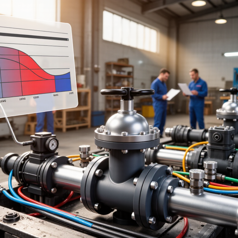
Reading the chart: At a constant flow of 10 L/min, hydraulic power dissipated across a throttling valve increases with pressure drop. Values are calculated using power (kW) = pressure drop (bar) × flow (L/min) ÷ 600. For selection, compare measured operating pressure drop while confirming the valve can provide stable control at the required flow. In 2026, options include manually adjusted flow controls and electronically controlled proportional valves with sensors; assess serviceability, contamination sensitivity, and control needs for your application.